 English
 中文
中文Most component datasheets include recommended PCB package information specifying the hole sizes suitable for that component, which is the most practical method for selecting PCB hole sizes. However, some datasheets only provide the component’s physical dimensions and pin diameter tolerances. In such cases, when we create the component package based solely on these physical dimensions, how should we select the hole sizes?
In PCB design, the aperture size of through-hole components and the size of their pads are critical parameters determining final assembly quality and product reliability. Precise aperture design not only forms the foundation for automated assembly but also ensures excellent soldering performance and long-term mechanical stability. Improper aperture selection may lead to a series of manufacturing challenges, such as component insertion difficulties, soldering defects, and potential reliability risks. This article aims to systematically outline the standard methods and core principles for PCB through-hole aperture design, assisting engineers in mitigating risks during the design phase and enhancing product first-pass yield.
Fundamental Principles of Aperture Design
The design of through-hole aperture size must strike a balance between the physical dimensions of component leads and manufacturing process tolerances. An aperture that is too small will prevent components from being inserted smoothly, increasing the cost and risk of manual rework, and may even damage component leads or PCB material during forced assembly. Conversely, an aperture that is too large will cause problems during the soldering process, such as insufficient solder fill, component positional shift, and reduced mechanical strength of solder joints.
There is a simple rule of thumb: add 0.2mm to the nominal pin diameter to determine the appropriate hole size. Why 0.2mm? Why not just add 0.05mm, or match the pin diameter exactly? Because component manufacturers apply tolerance ranges to physical dimensions. Actual sizes will differ from nominal values.
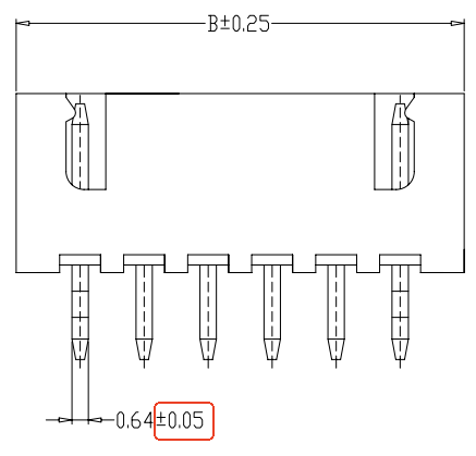
The tolerance for most pin diameters is approximately ±0.05mm. A 0.2mm allowance reliably accommodates this variation, ensuring components can be inserted stably.
IPC2221: Industry Standard for Aperture Design
The International Electronics Manufacturing Alliance (IPC) provides authoritative guidance standards for PCB design and manufacturing. According to relevant standards such as IPC-2221A/B, the calculation of through-hole diameter is based on the following core formula:
Minimum Hole Size = Maximum Lead Diameter + Tolerance Allowance
IPC defines three levels of tolerance allowances based on the product’s application grade and component density to accommodate different design requirements:
- Level A (Universal Design/Preferred): Offers maximum manufacturing tolerance, suitable for most standard-density product designs, and provides optimal manufacturability.
Calculation Formula:
Maximum pin diameter + 0.25mm (10 mils)
- Level B (Medium Density Design/Standard): Reduced tolerances suitable for designs with higher component density, offering a balanced choice between performance and manufacturability.
Calculation formula:
Maximum pin diameter + 0.20mm (8 mils)
- Level C (High-Density Design/Minimum): Offers the tightest tolerances, specifically designed for high-density or complex circuit boards with extremely limited space. Selecting this level demands higher process capability from manufacturers and requires careful evaluation.
Calculation Formula:
Maximum pin diameter + 0.15mm (6 mils)
Note that when performing calculations, the maximum pin dimensions specified in the component datasheet must be used as the reference, not the “typical values.” This is a critical preventive measure to avoid assembly issues caused by variations between component batches.
Methods for Handling Non-Circular Pins
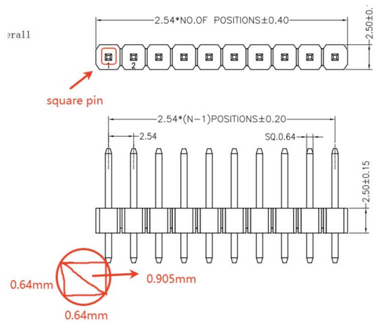
For pins with square or rectangular cross-sections, the effective diameter is equal to the length of its diagonal. During design, the maximum diagonal dimension must first be determined through geometric calculation (using the Pythagorean theorem), then substituted into the aforementioned IPC formula as the “maximum pin diameter.”
For a rectangular pin with cross-sectional dimensions a and b:
Maximum effective diameter (diagonal) = √(a² + b²)
For example, in the component shown below, if the datasheet does not specify a recommended PCB package hole diameter, the maximum effective diameter is √(0.64² + 0.64²) = 0.905 mm. A reasonable package hole diameter value is 0.905 mm + 0.2 mm = 1.1 mm.
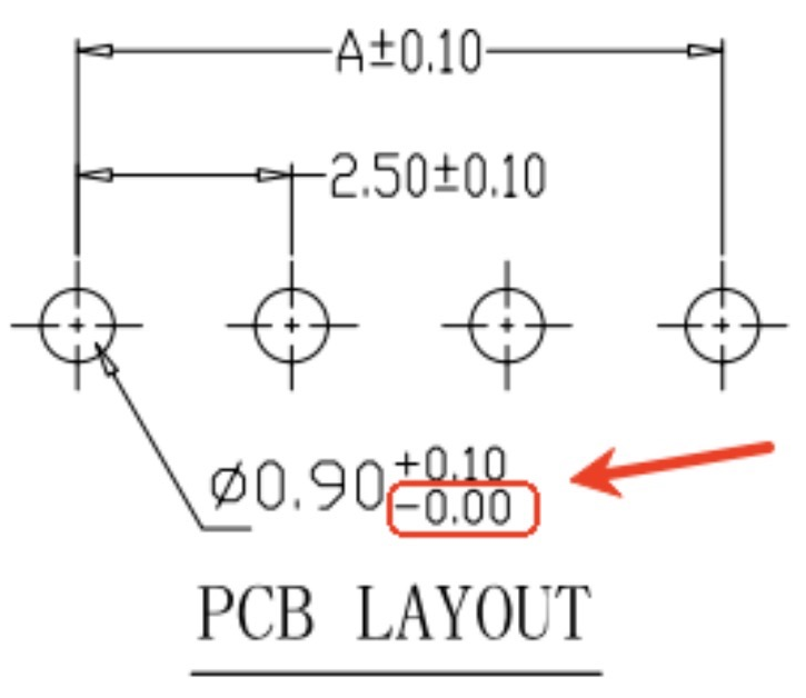
Unidirectional tolerance
If the data sheet specifies only positive tolerances (e.g., 0.9mm + 0.1mm / -0), use: Standard + all positive tolerances. For example, the aperture in the figure below = 0.9mm + 0.1mm = 1.0mm.
Collaborative Design of Pad Dimensions
After determining the hole diameter, a matching pad must be designed to ensure the formation of a reliable annular ring. The width of the annular ring directly affects the strength and electrical conductivity reliability of the solder joint. The formula for calculating the pad diameter is typically:
Pad Diameter = Hole Diameter + 2 × (Minimum Annular Ring Width Requirement) + (Manufacturing Tolerance)
According to IPC standards, the minimum trace width should generally not be less than 0.15mm (6 mils). During design, the manufacturer’s process capabilities should be comprehensively considered, adhering to Design for Manufacturability (DFM) principles and engaging in necessary technical communication with the manufacturer.
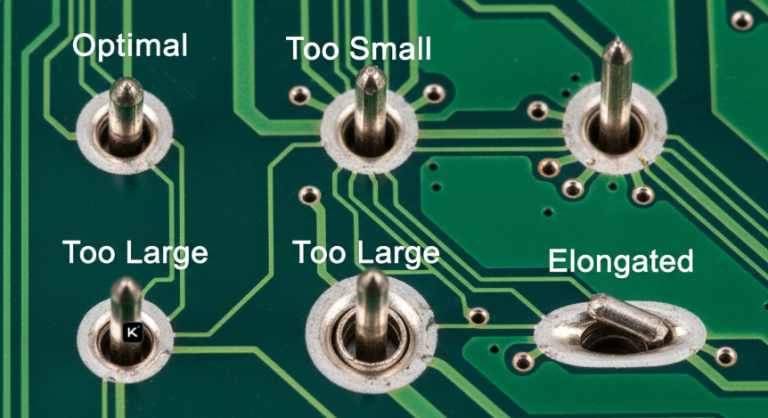
The improperly designed product may cause potential manufacturing defects
- Assembly Difficulties and Pin Damage: Excessively small hole diameters directly cause automated insertion failures, while manual correction processes are prone to damaging pins or hole walls.
- Component Positioning Deviation: Excessively large hole diameters may cause components to tilt or shift during conveyance and wave soldering, compromising circuit performance and product appearance.
- Soldering defects: An excessive hole-to-lead ratio impedes proper solder capillary action filling, leading to voids, cold solder joints, or incomplete solder coverage—creating long-term reliability risks.
Conclusion
Precise PCB via aperture design serves as the bridge connecting design and manufacturing. By adhering to IPC standards and implementing rigorous design processes, engineers can significantly enhance product manufacturability, assembly efficiency, and ultimate reliability. This approach reduces production costs and accelerates time-to-market.