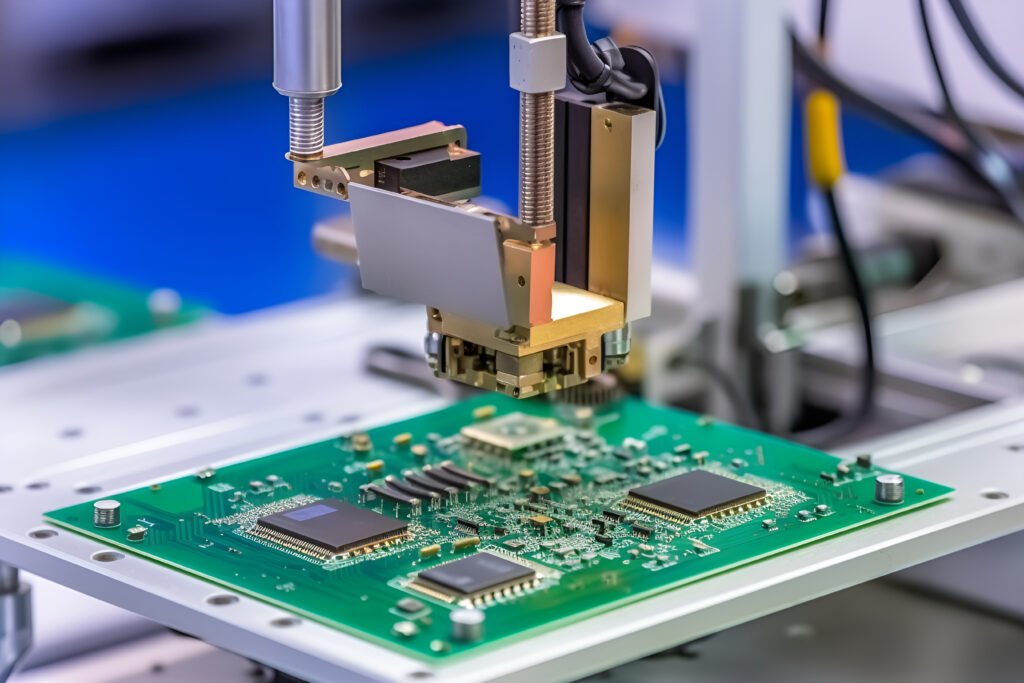
High speed PCB design plays a vital role in the advancement of modern technology, helping to develop faster and more efficient electronic devices. Whether it’s high-performance computing, telecommunications or consumer electronics, quick PCBs are at the heart of these cutting-edge technologies. To ensure the seamless transmission of high frequency signals and maintain optimum performance, the design of high-speed PCBs requires careful consideration of a number of factors, including controlled impedance, signal routing, power integrity, EMI/EMC mitigation and thermal management. By addressing these issues, quick-speed printed circuit board can effectively overcome the challenges associated with high-frequency signals and meet the performance requirements of modern electronic systems. This article begins with two key factors: signal integrity and thermal management.
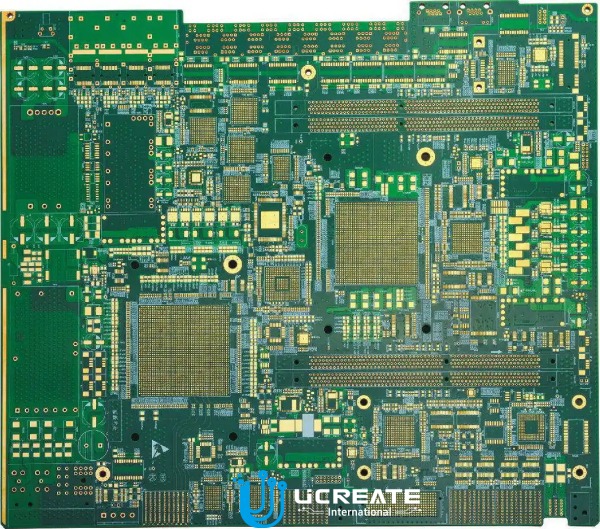
What are High-Speed PCBs?
A High Speed PCB is a special type of printed circuit board designed to carry high frequency signals with minimal signal attenuation or loss of signal integrity. They are designed to meet the unique challenges posed by high frequency signals found in applications such as high performance computing, telecommunications, networking equipment, data centres and advanced consumer electronics. The range of applications for fast-paced signal integrity board is very broad and our production department can reach a monthly capacity of 200,000 square metres.
High-velocity circuit boards differ from regular PCBs in terms of their design considerations, materials, and layout techniques. These boards are specifically optimized to minimize the effects of signal distortions, reflections, and crosstalk that can occur at higher frequencies.
Ensuring Signal Integrity in High-Speed PCBs?
1. What is Signal Integrity?
Signal integrity refers to the ability of a signal to retain its quality and integrity as it travels through a transmission medium, such as traces on a PCB or cables. In the context of rapid PCB design, signal integrity is crucial for the accurate transmission and reception of high-frequency signals.
Signal integrity is determined by various factors, including impedance control, proper routing, ground plane design, termination techniques, and minimizing the impact of noise and interference. Maintaining signal integrity ensures that the transmitted signals arrive at their destination without distortion, degradation, or errors, thus enabling reliable communication and data transfer in high-speed electronic systems.
2. Factors Affecting Signal Integrity
Several factors can compromise signal integrity in turbocharged PCBs. Understanding and addressing these factors is essential for maintaining reliable signal transmission.
(1)Impedance Mismatches
When the characteristic impedance of a transmission line does not match the impedance of the connected devices or the surrounding environment, impedance mismatches can occur. These mismatches lead to signal reflections, resulting in signal degradation and distortion.
(2)Reflections
Signal reflections occur when a portion of a signal is reflected back due to impedance mismatches, signal discontinuities, or improper termination. Reflections can cause interference, signal distortions, and timing errors, impacting the accuracy of the transmitted signal.
(3)Crosstalk
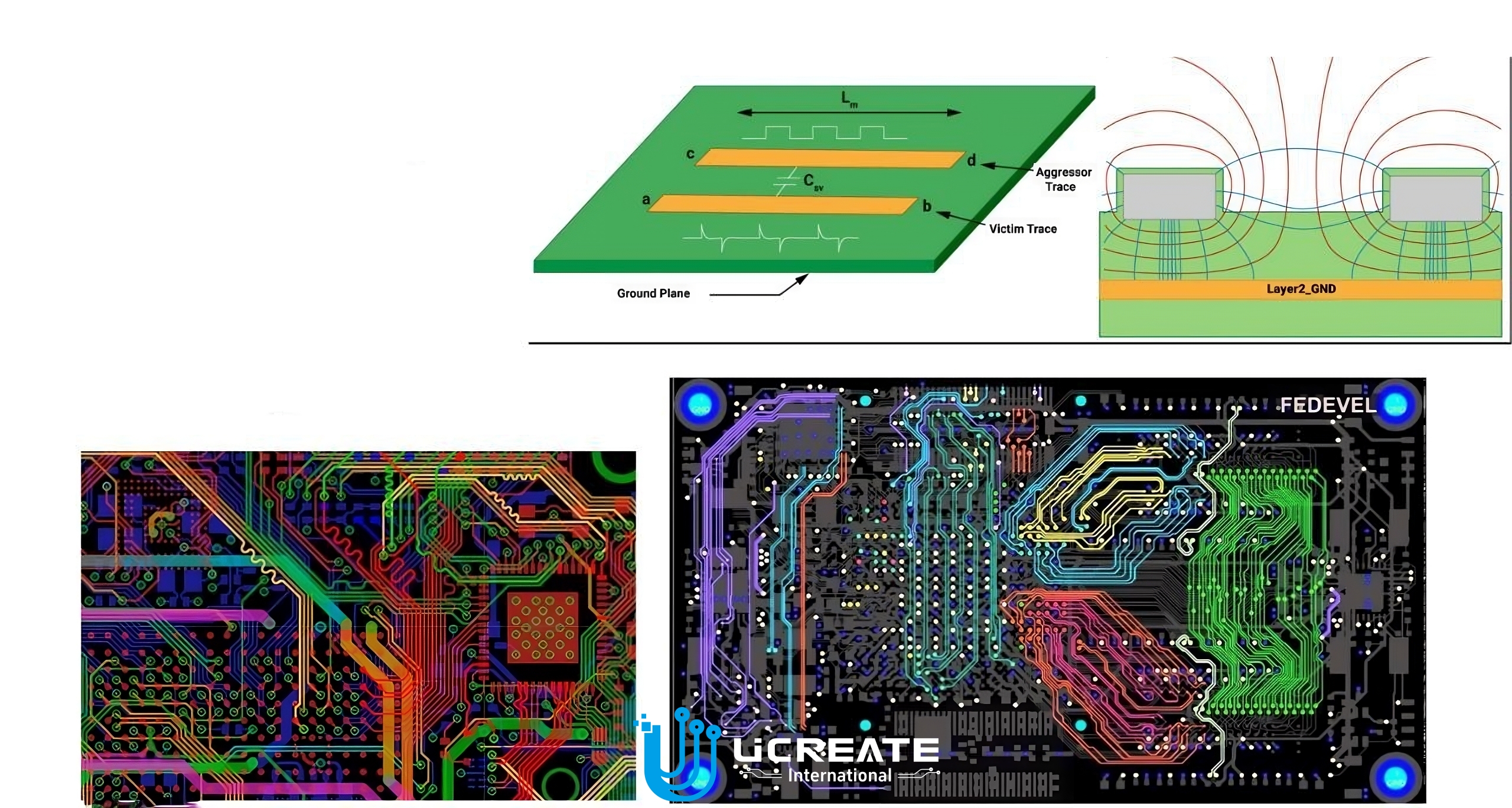
Crosstalk is the unwanted coupling of signals between adjacent traces on a PCB. It occurs due to electromagnetic fields generated by high-speed signals interfering with neighboring traces. Crosstalk can lead to signal interference, noise, and signal integrity degradation.
(4)Electromagnetic Interference (EMI)
EMI refers to the unwanted electromagnetic radiation or noise that can interfere with signals. EMI can arise from external sources or be generated within the PCB itself. When quick-frequency signals are subjected to EMI, it can result in signal degradation, increased noise, and errors in signal reception.
3. Techniques for Maintaining Signal Integrity
To ensure signal integrity in high-performance PCB design, several techniques are employed. These techniques help minimize the impact of factors that can compromise signal quality.
(1)Controlled Impedance
Controlling the impedance of transmission lines to match the characteristic impedance of the connected devices and the surrounding environment is crucial. This involves careful selection of trace widths, spacing, and dielectric materials to achieve the desired impedance and minimize impedance mismatches.
(2)Proper Routing
Careful routing of rapid response signals is essential to minimize signal distortions. Techniques such as length matching, differential signaling, and controlled impedance routing help maintain signal integrity, reduce skew, and minimize crosstalk.
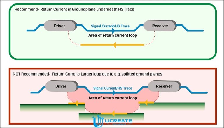
(3)Ground Plane Design
Implementing a solid ground plane or ground structure beneath or adjacent to signal traces
provides a low-impedance return path for the high-velocity signals. This helps minimize noise, reduce crosstalk, and improve signal integrity.
(4)Termination Techniques
Proper termination of transmission lines is necessary to prevent signal reflections. Techniques such as series termination, parallel termination, or termination resistors matching the characteristic impedance help minimize signal reflections and maintain signal integrity.
(5)Decoupling Capacitors
Placing decoupling capacitors near high-speed components helps provide stable and noise-free power supply. This reduces voltage fluctuations, improves power integrity, and minimizes the impact of noise on signal quality.
By implementing these technologies, our Ucreate International technology department maintains signal integrity, ensuring the accurate transmission and reception of high frequency signals while minimising the effects of impedance mismatch, reflections, crosstalk and electromagnetic interference.
The Role of Thermal Management in High Speed Circuit Board Design
1. Importance of Thermal Management
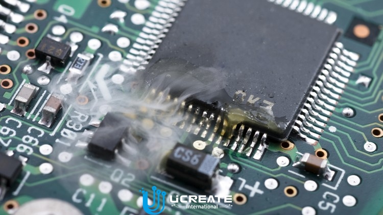
Thermal management is of utmost importance in agile PCB design due to the significant heat generated by high-frequency components and power dissipation.
(1)Preventing Component Failure
Excessive heat can lead to component overheating, which can cause accelerated aging, reduced lifespan, and even component failure. By managing heat effectively, the operating temperature of components can be maintained within safe limits, ensuring their reliability and longevity.
(2)Maintaining Performance
High temperatures can negatively impact the performance of electronic components and systems. Excessive heat can lead to thermal expansion, increased resistance in conductive pathways, and reduced signal integrity. By controlling temperatures, the performance of ultra-fast PCBs can be preserved, minimizing signal degradation and maintaining optimal system operation.
(3)Avoiding Signal Integrity Issues
Temperature variations can cause changes in the electrical properties of PCB materials, resulting in impedance variations and signal integrity issues. Thermal management techniques help maintain consistent electrical characteristics, ensuring reliable signal transmission and minimizing the impact of temperature-induced impedance changes.
(4)Enhancing Efficiency
Heat can reduce the efficiency of electronic components, leading to wasted energy and increased power consumption. Effective thermal management helps dissipate heat efficiently, reducing energy losses and improving the overall efficiency of express PCBs.
2. Thermal Considerations in High-Speed PCB Design
In high-performance PCBs, heat can originate from various sources, including power dissipation and high-frequency components:
(1)Power Dissipation
Power-hungry components such as processors, FPGAs, and high-speed memory modules generate significant heat due to power dissipation. The high-frequency signals flowing through the power delivery network also contribute to heat generation.
(2)High-Frequency Components
Active components operating at high frequencies, such as RF transceivers or high-speed data interfaces, can generate heat due to their internal switching operations. These components require careful thermal management to prevent performance degradation and ensure reliable operation.
The impact of heat on signal integrity and overall system performance in quick speed printed circuit board includes:
- Signal Degradation
High temperatures can cause changes in the electrical characteristics of PCB materials, leading to variations in impedance along transmission lines. This can result in signal reflections, increased signal loss, and reduced signal quality, ultimately affecting the accuracy and reliability of high-rate signals transmission.
- Timing and Skew Issues
Heat-induced variations in electrical characteristics can cause timing mismatches and signal skew, leading to timing errors and signal misalignment. This can result in data corruption, increased jitter, and reduced system performance.
- Increased Crosstalk
Heat can exacerbate crosstalk issues in speedy PCBs. As the temperature rises, the conductivity of the PCB substrate may change, affecting the electromagnetic fields and increasing the coupling between adjacent traces. This can lead to crosstalk-induced noise, interference, and signal degradation.
3. Techniques for Effective Thermal Management
- Thermal Vias
Thermal vias are strategically placed vias that connect the top and bottom layers of the PCB, providing a thermal pathway for heat dissipation. They help conduct heat away from heat-generating components and distribute it to larger ground planes or heat sinks for efficient dissipation.
- Heat Sinks
Heat sinks are passive cooling devices that absorb and dissipate heat from high-power components. They are typically made of thermally conductive materials, such as aluminum or copper, and are mounted on top of heat-generating components to increase their surface area and enhance heat dissipation.
- Proper Component Placement
Placing high-power components and heat-generating devices in areas with good airflow and proximity to heat sinks or thermal vias can aid in effective heat dissipation. Avoiding overcrowding and ensuring sufficient spacing between components also help prevent localized heat buildup.
- Thermal Pads and Paste
Thermal pads or paste provide improved thermal conductivity between heat-generating components, such as power devices, and heat sinks or PCB layers. These materials help enhance heat transfer and reduce thermal resistance, improving overall thermal management.
- Thermal Analysis and Simulation
Utilizing thermal analysis and simulation tools allows for the prediction and evaluation of heat dissipation in quick PCB designs. This helps identify potential hotspots, optimize thermal management strategies, and ensure that operating temperatures remain within acceptable limits.
Ucreate International’s manufacturing facilities use these thermal management technologies to effectively dissipate heat and prevent overheating, component failure and performance degradation. This ensures reliable operation and signal integrity of high speed PCBs.
Conclusion
High-speed PCB design requires careful consideration of two critical factors: signal integrity and thermal management. Signal integrity ensures the accurate transmission and reception of high-frequency signals, while thermal management prevents excessive heat that can lead to component failure and reduced performance.
The implementation of signal integrity and thermal management considerations is critical in the design of high-speed printed circuit boards. Ignoring these factors can result in unreliable operation, signal degradation, reduced system performance and premature component failure. By carefully considering these factors, Ucretae International’s design department enables fast PCB designs that deliver reliable, efficient performance in demanding applications.
By prioritising signal integrity and thermal management, designers can ensure accurate transmission of high frequency signals while maintaining optimum operating temperatures. This approach enables high performance PCB designs that meet the demands of today’s high-speed electronic systems.

 English
 中文
中文


