 English
 中文
中文Signal integrity is a crucial concept in the PCB (printed circuit board) design process of modern electronic devices.With the increasing speed and complexity of electronic products, signal integrity has gradually become one of the key factors restricting the quality of PCB design and manufacturing.
This article will take you in-depth understanding of PCB prototyping in the signal integrity, to understand its main factors affecting the signal integrity of the common causes of the problem.
I. What is SI
Signal Integrity (Signal Integrity, SI) simply means that the signal transmission on the PCB, whether to maintain its original waveform, amplitude, phase and other characteristics, but not because of a variety of interfering and influencing factors and distortion or degradation of the phenomenon.In modern high-speed digital circuits and radio frequency circuits, signal transmission speed is very fast, high frequency, signal transmission on the PCB is no longer a simple “on” and “off” process, but a complex electromagnetic process.
Good signal integrity means that the signal can be transmitted accurately on the PCB, so that the various parts of the electronic equipment can work together to ensure the stability and reliability of the system.Once the signal integrity problem occurs, it may lead to signal distortion, BER increase, electromagnetic interference and other problems, thus affecting the performance and function of electronic equipment.
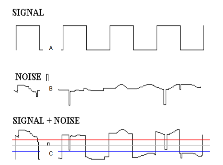
In the figure below, the original signal A becomes C due to the introduction of noise B, which leads to misinterpretation of the data and may trigger incorrect operation, which may cause deviation and impact on the electronic equipment.
II. Factors affecting signal integrity
1. Reflection
Reflection is the phenomenon of energy return on the transmission line formed by the impedance mismatch betweenthe source and load side of a signal during transmission.When a signal enters an impedance region from one impedance region to another, a reflection occurs if the impedance of the two regions is not continuous.Reflections not only reduce the energy of the signal, but may also cause signal superposition and distortion, affecting the integrity of the signal.
2. Crosstalk
Crosstalk refers to the mutual interference between adjacent signal lines on a PCB due to electromagnetic coupling.When a signal on a signal line changes, it generates an electromagnetic field around it, and this electromagnetic field induces a voltage on the neighbouring signal lines, thus interfering with the signals on the neighbouring signal lines.Crosstalk can lead to misjudgement and malfunctioning of signals and is one of the most important factors affecting signal integrity.
3. Power Losses
Power loss is the energy loss due to dielectric loss, radiation loss and other reasons during the transmission of the signal on the PCB.As the transmission distance increases and the signal frequency increases, the power loss will be more significant.Power loss reduces the amplitude of the signal and increases the noise, thus affecting the quality of the signal and the transmission distance.
III. Reasons for signal integrity problems
1. Impedance Mismatch
Impedance mismatch is one of the most common causes of signal integrity problems.In PCB design, if the impedances of the source and load side of the signal are not well matched, reflections will occur, thus causing signal distortion and crosstalk.In order to ensure the integrity of the signal, it is usually necessary to add matching resistors and other components at the source and load ends to match the transmission impedance of the signal with the characteristic impedance of the transmission line.
2. Transmission Line Effect (TLE)
When the rise and fall times of a signal are less than 1/6 of the length of the signal’s transmission path, the signal exhibits significant high-speed characteristics, at which point the transmission line effect becomes apparent.The transmission line effect leads to problems such as signal delay, reflection and crosstalk, which seriously affects the quality of the signal.Therefore, in PCB design, it is necessary to reasonably select the type of transmission line and wiring method according to the frequency of the signal and the length of the transmission path in order to reduce the impact of the transmission line effect.
3. Crosstalk
Crosstalk is mutual interference due to electromagnetic coupling between neighbouring signal lines.In the process of PCB layout and wiring, if the spacing of signal lines is too small, the spacing is unreasonable, or the wiring direction is inconsistent, it is easy to generate crosstalk.In order to avoid the impact of crosstalk, it is necessary to reasonably plan the layout and wiring scheme of the signal lines, to maintain the proper spacing and direction consistency between the signal lines.
4. Ground Bounce and Power Supply Noise
Ground bounce and power supply noise arise due to the instability of the power supply and ground loop in a system.In high-speed digital circuits, when multiple signals are switched at the same time, instantaneous current variations are generated. These current variations generate voltage drops and spike noise in the power supply and ground paths, which lead to ground bounce and power supply noise.In order to reduce the impact of ground bounce and power supply noise, it is necessary to reasonably design the layout of the power supply and ground, and use measures such as decoupling capacitors to filter out the noise.
5. Signal attenuation
Signal attenuation is the gradual reduction of signal energy due to dielectric loss, radiation loss and other reasons during transmission on the PCB.Signal attenuation will lead to a reduction in signal amplitude and an increase in noise, thus affecting the quality of the signal.In order to reduce the impact of signal attenuation, it is necessary to reasonably select the dielectric material and wiring structure to reduce the loss of the signal in the transmission process.
6. Thermal effect
During the operation of electronic equipment, heat is generated due to the passage of electric current, and this heat affects the components and circuits on the PCB, i.e. the thermal effect.The thermal effect may lead to changes in the parameters of the components, thus affecting the performance and stability of the circuit, and also affecting the quality of signal transmission.Therefore, in PCB design and layout, it is necessary to reasonably consider the heat dissipation problem to ensure that electronic equipment can operate normally.
IV. Summary
In summary, signal integrity is one of the key concerns in PCB design.Understanding the concept of signal integrity, the factors affecting it, and the causes of the problem will help engineers take effective measures to ensure the quality and reliability of the signal in the PCB design process, thus improving the performance and stability of electronic devices.
If you have difficulty in solving problems or doubts in PCB design and layout, please feel free to contact us, our company will have professional PCB designers to provide you with one-stop service to assist you from design, board making to assembly.