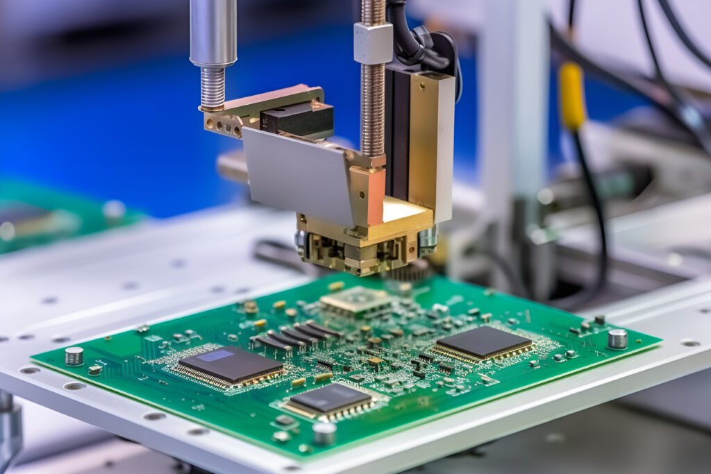
AOI (Automated 0ptical Inspection), namely automatic optical detection, is a method of automatic detection of printed circuit board (PCB) using optical principle and image processing technology. It can quickly and accurately find the defects on PCB, including short circuit, open circuit, displacement, dislocation, offset, welding quality and other problems, is a very important quality control link in the production process of PCB.
In the face of more severe manual inspection problems brought about by the reduced size of printed circuit boards, many original equipment manufacturers (OEMs) are actively adopting AOI technology to meet this challenge. As a key means of defect control, AOI can accurately identify and eliminate defects at an early stage of the assembly process to strengthen process management. By detecting defects as early as possible, it can not only prevent defective products from flowing into the subsequent assembly link, but also use AOI to reduce maintenance costs and avoid the circuit board scrap caused by irreparable repair, so as to improve the overall manufacturing efficiency and yield rate.
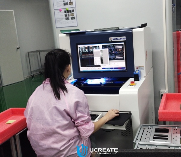
According to the different working methods, AOI can be divided into online AOI inspection and offline AOI inspection. Online AOI inspection is a real-time inspection of boards on the SMT production line as they pass through the AOI equipment to detect and correct problems in time; offline AOI inspection is to test the offline boards to find and repair problems.
The main content of AOI detection, including multiple components, missing parts, wrong parts, monument, side stand, side stand, reverse stand, paste, replacement, extreme reverse, IC, pin bending, text recognition, as well as solder tin, less tin, Wuxi, virtual welding, short circuit, tin ball, floating and other problems. AOI can also realize the detection of different spacing and density plates through high-speed precision visual processing technology.
Comparison of AOI inspection and manual inspection
| Manual Inspection | AOI Inspection | ||
| PCB<18*20 and less than 1,000 pads | Manual | important | complementary check |
| Time | normal | normal | |
| Sustainability | different for each individual | good | |
| Reliability | different for each individual | preferably | |
| Accuracy | different for each individual | high rate of misdirection | |
| PCB<18*20 and more than 1,000 pads | Manual | important | complementary check |
| Time | long | Short | |
| Sustainability | poor | good | |
| Reliability | poor | preferably | |
| Accuracy | different for each individual | high rate of misdirection | |
| PCB Quartering (each station is responsible for inspecting one quarter of the board) | |||
Main features of AOI
1, High-speed detection system, independent of the PCB board assembly density.
2, Fast and convenient programming system, in its graphical interface, the use of placement data for automatic data detection, the use of component databases for rapid processing of inspection data.
3, Use a wealth of special multi-function detection algorithms and binary or grayscale optical image processing technology for detection.
4, According to the instantaneous change of the position of the detected component, the detection window is automatically corrected to achieve high-precision detection.
5, Through the use of ink directly marked on the circuit board, or in the operation of the display with a graphical error marking, two ways to check the detection of electricity.
Types of components that can be inspected:
1, Rectangular chip components (0805 or larger): AOI can detect these components and determine whether there are defects such as poor soldering, reverse polarity, component flipping, and so on.
2, Cylindrical chip components: AOI can detect these components and determine whether there are defects, such as poor soldering, polarity reversal, component flip and so on.
3, Tantalum electrolytic capacitors: AOI can detect the polarity of tantalum capacitors, whether there is bad welding and other problems.
4, Coil: AOI can detect the coil, whether there is bad welding, reverse polarity and other problems.
5, Transistor: AOI can detect the polarity of the transistor, whether there is bad welding and other problems.
6, Rows: AOI can detect the polarity of rows, whether there are problems such as bad soldering.
7, QFP, SOIC (0.4mm pitch or larger): AOI can detect the polarity of these components, whether there are problems such as poor soldering.
8, Connectors: AOI can detect the polarity of the connector, whether there are bad soldering and other problems.
9, Shaped components: AOI can detect these irregularly shaped components, whether there are poor soldering, polarity and other problems.
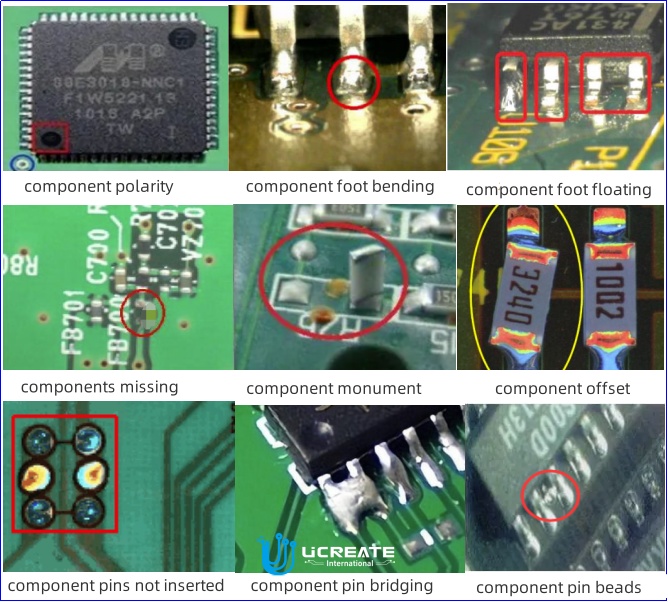
Items that can be tested
1, No components: AOI can detect if there are missing components on the PCBA, regardless of the type of PCBA.
2, Not centered (detached): AOI can detect whether the components are centered, whether there is a detached situation.
3, Reverse polarity: AOI can detect whether the polarity of the components is correct, whether there is a situation of reverse polarity.
4, Upright: AOI can detect whether the components are upright, whether there is poor soldering and other problems.
5, Weld crack: AOI can detect the presence of weld cracks.
6, Component tilt: AOI can detect whether the component is flipped, that is, the top and bottom have different characteristics.
7, The wrong components: AOI can detect whether there are different characteristics between the components, whether there is the case of mislabeling.
8, Less tin: AOI can detect the presence of less tin.
9, Warping: AOI can detect the presence of warping.
10, Continuous welding: AOI can detect 20μm and more continuous welding.
11, No solder: AOI can detect the presence of no solder.
12, More tin: AOI can detect the presence of more tin.
It is not only the process, but also the design that affects the quality of the reflow soldering, for example, poorly designed pad sizes will affect the reflow soldering yield.
Therefore, at Ucreate engineers will perform free DFM testing on all PCB design files Before SMT, which can avoid the problem of components not being assembled due to unreasonable design. Welcome send us your Gerber file to Sales@ucpcba.com for DFM test.

 English
 中文
中文


