 English
 中文
中文1. Waveform testing
Waveform testing, the most basic method of signal integrity testing, is usually performed using an oscilloscope.By testing the characteristics of the waveform, it analyses the amplitude, edge time and other indicators to see if they comply with the protocol standards (e.g. LVDS, CML), focusing on overshoots, undershoots and rise/fall times, and is suitable for single-signal line quality assessment.
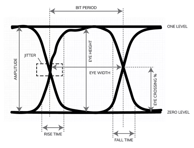
2. Eye diagram test
Eye diagram analysis is one of the most commonly used tools for exploring signal integrity.Eye diagram is a method to view the response of digital circuits over time. It uses an oscilloscope to input repetitive signals into the circuit being analysed and measure the output signal over time to analyse the eye height, eye width and noise tolerance, and to assess the quality of the signal from a serial bus (e.g. PCIe, USB).When using the eye diagram test, you need to pay attention to the number of test waveforms, especially for the interface eye diagram to determine whether the specification is met, the number is too small, the waveform jitter is relatively small.Under normal circumstances, the best number of test waveforms is about 3000, with an oscilloscope with a bandwidth ≥ 3 times the signal frequency.
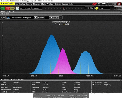
3. Jitter test
Jitter test quantifies signal cycle jitter (Jitter) and timing offsets through time interval analyser to locate clock signal stability problems, commonly used in DDR, high-speed SerDes interface timing tolerance verification.
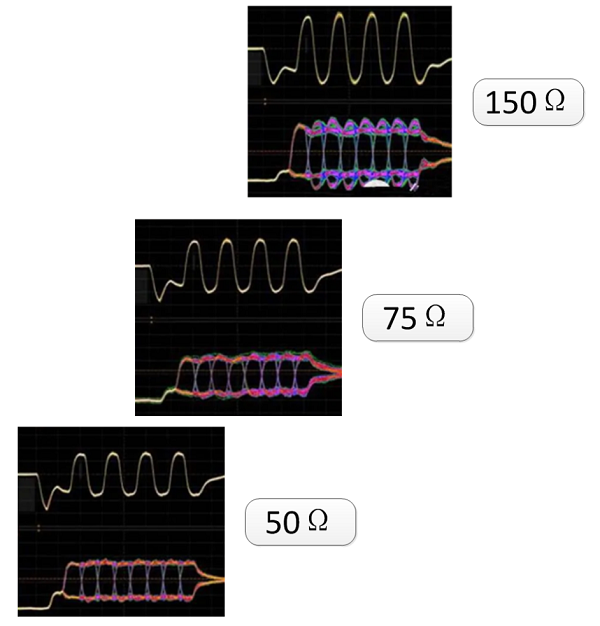
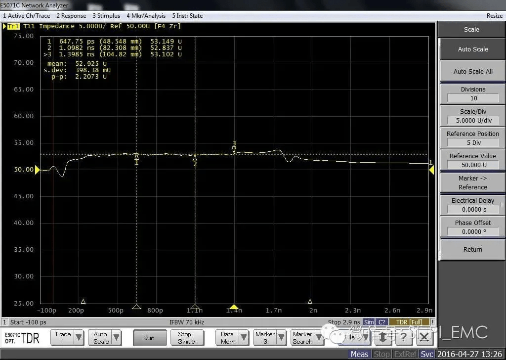
4. TDR test
TDR testing is currently used for PCB signal lines, and device impedance testing, such as single-ended signal lines, differential signal lines, connector cables, and so on.Usually this type of test has the requirement that it is closely related to the actual application.
5. Timing test
Timing tests synchronise the measurement of parameters such as signal delay, clock skew (Skew), etc., to verify the matching of the timing window of a parallel bus (e.g., DDR4), Avoiding data conflicts leads to system failures.
6. Spectrum testing
Spectrum test through the spectrum analyser to detect the signal harmonics, spurious noise and other frequency domain characteristics, locate the root cause of EMI exceeds the standard, applicable to RF circuits and high-speed digital signal radiation interference analysis.
7. Frequency domain impedance test
Frequency domain impedance testing uses a vector network analyser (VNA) to measure the impedance characteristics of a transmission line at different frequencies and to verify the impedance continuity of high-frequency signals (e.g. millimetre waves).
8. Transmission line loss test
Transmission line loss testing measures the amount of signal attenuation in a PCB alignment through a VNA or TDR, assessing whether the link loss of high-frequency signals (e.g., HDMI 2.1) meets the insertion loss (IL ) specification.
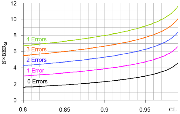
9. BER test
BER testing uses a BER meter to send specific data patterns and count the bit error rate (BER) at the receiving end to verify the reliability of high-speed interfaces (e.g., PCIe Gen5). It is usually performed in conjunction with eye diagram testing.
In practical engineering applications, the use of the test means described above, need to be based on the object under test, case-by-case analysis.Some need to consider the interface, some need eye diagram test, impedance test, BER test and so on.In addition there are ordinary circuit boards, you can use waveform test, timing test, etc..If the design of the circuit has high-speed signals, you can use the TDR test, for high-speed serial signals, clock signal lamps, you can also use the jitter test and so on.
If you have any confusion and need about PCB design and manufacturing, please feel free to contact us.