 English
 中文
中文
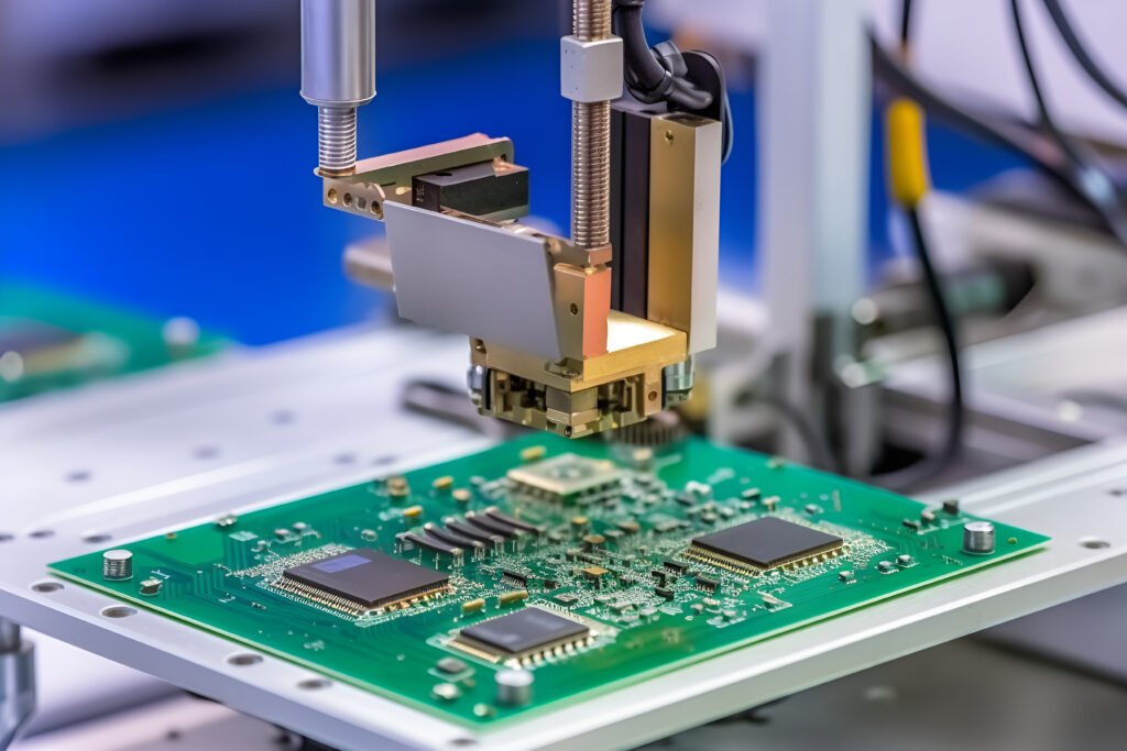
Printed Circuit Boards are essential gadgets in all electronic devices. Regardless of whether the said gadgets are for domestic or industrial purposes, they still require PCBs. Besides electronically connecting, PCBs also bring about mechanical support to electric components.
A majority of us would easily recognize printed circuit boards when we bump on them. They are small green chips that are covered by copper parts and traces. The traces are like super-highways that lead traffic in some direction.
But are you aware of a printed circuit assembly process? Unfortunately, a lot of suppliers, manufacturers, and PCB enthusiasts don’t know much about this. This article points out ten notes in a PCB assembly process.
1. Character placement is unreasonable
The character cover pad SMD soldering piece brings great inconvenience to the soldering of the component and the on-off test of the printed board.
The character design is too small, which makes screen printing difficult, and the over-construction causes characters to be stacked on each other, making it difficult to distinguish.
2. the processing industry can not clarify
The single-panel design is on the TOP layer. If it is not clarified, it will be done in reverse. The fabricated board is also lacking in good soldering.
For example, a four-layer pcb board design uses four layers of TOP mid1 and mid2 bottom, but the processing is not placed at the same time, which requires clarification.
3. Draw pads with padding
When designing the circuit, the pad can be traced by the DRC, but the processing is not possible, because such a pad can not directly generate solder resist data. When the solder resist is applied, the pad area will be solder resist. Covering, making the device difficult to solder.
4. Single-sided pad aperture setting
Single-sided pads are generally not required to be drilled. If drilling is required, they should be marked and their aperture should be designed to zero. If a numerical value is designed, perhaps when the drilling data occurs, this position presents the coordinates of the hole and the problem is presented.
Single-sided pads should be marked if they need to be drilled.
5. Stacking of pads
The stacking of the pads (except for the surface pads) means that the holes are stacked. During the drilling process, the drill bit is broken due to repeated drilling at one place, causing damage to the holes.
In the multi-layer pcb board, two holes are stacked, one hole should be the isolation plate, and the other hole is the connection plate, otherwise the film will be represented as the isolation disk after the negative film is formed, which will be scrapped.
6. The abuse of the graphics layer
Unusual wiring is done on some graphics layers, that is, four-layer boards are designed with more than five layers, which will form a misinterpretation.
In the design time chart, the Protel software is used as an example to draw the lines of each layer with the Board layer, and use the Board layer to mark the line. When the data is being drawn, the missing layer is not selected. The open circuit may be short-circuited by selecting the label line of the Board layer, so the design layer adheres to the integrity and clarity of the graphic layer.
In contrast to conventional designs, such as the component surface design in the Bottom layer, the welding surface design in the Top, creating unnecessary trouble.
7. The electric ground layer is the connection and the flower pad.
Because of the power supply designed as a flower pad method, the ground layer is the opposite of the image on the practical printed board, and all connections are isolated lines, which should be very clear to the designer. When drawing several sets of power supply or isolation lines of several grounds, be careful not to close them to avoid short circuit between the two groups.
8. There are too many filler blocks in the design or the filling block is filled with very thin lines.
There is a loss of sight in the raw light painting data, and the light painting data is not complete.
The filling block is drawn one by one in the line of light painting data processing, so the amount of light drawing data generated is quite large, adding the difficulty of data processing.
9. The spacing of the area grid is too small
The edge between the large-area grid lines and the same line is too small (less than 0.3mm). In the manufacturing process of the printed board, the image transfer process easily occurs after the shadow is formed, and a lot of broken film adheres to the board to form a broken line.
10.Do not understand the design of the frame
The customer has designed the outline lines in the Keep out layer, the Board layer, the Top over layer, etc., and these outline lines do not coincide, which makes it difficult to determine which shape line the PCB reverse engineer is based on.